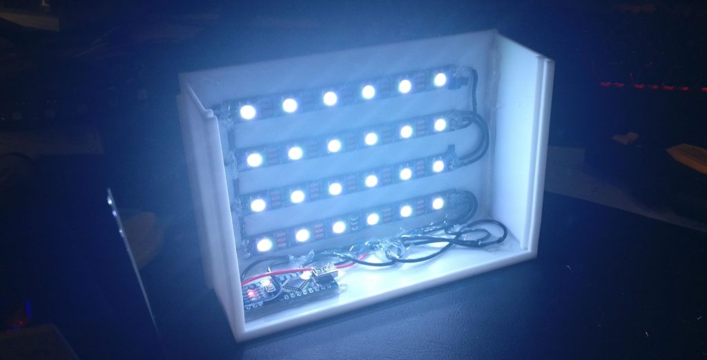
A while ago I was throwing together a quick prototype of a lithophane lamp, where one can slide in different printed plates @ 9x13cm (3½ × 5 in). To provide enough and customizable lighting I chose some WS2812 driven RGB led-strips. Since I didn’t want to include an external button or switch, I was facing the challenge on how to control the color/brightness of the LEDs.
Providing user input via reset-button
Since I was using an Arduino Nano I decided to use the inbuilt reset-button. The idea was to cycle through a few possible, pre-programmed colors with every reset. The main problem? Avoiding color changes whenever one turns the lamp off/on. After all, it should keep the same color (you’ve selected) every time you turn it on and only cycle if one really presses the reset-button!
The MCU Status Register (MCUSR)
To distinguish between a reset-button press and a normal power-on one can use the MCUSR. As given in the ATmega328 datasheet (chapter 10), there are four possible resets that are being detected:
- Power-on reset (POR)
- External reset (EXTR)
- Watchdog system reset (WDR)
- Brown-out reset (BOR)
You can read all the specifics about those in the datasheet (including ways to influence the brown-out voltage – see Table 28-5. BODLEVEL, etc.). The one we care about is the external reset:
“The MCU is reset when a low level is present on the RESET pin for longer than the minimum pulse length.“
So, whenever we press the reset-button our MCU is being reset, and a specific bit (EXTRF) in the MCUSR can be used to detect that.
Using the EEPROM to manage our color choices
Now we know that it should be possible to detect pressing the reset-button we need to actually be able to cycle through different colors – even after a power-down. Using the inbuilt EEPROM (read more here) this is quite easy:
- We use a single address to save our color
- We use a single address to save our brightness
Every time we detect a user input (the user presses the reset-button) we decrease our brightness by a fixed value. As soon as it hits 0 we reset it to full brightness and cycle to the next color. BOOM. A color-controllable lamp without any external controls.
A simple implementation
To provide you with a starting point I’ve thrown together a simple example that you can expand on. I’ve stripped away the actual LED-control, if you are interested in that, take a look at the Adafruit NeoPixel library.
#include "EEPROM.h"

// define our EEPROM addresses
#define ADDR_COLOR       0
#define ADDR_BRIGHTNESS  1

void setup() {
  // immediately grab and clear the MCUSR
  byte mcusr = MCUSR;
  MCUSR = 0;

  // read the color and brightness from EEPROM
  byte brightness = EEPROM.read(ADDR_BRIGHTNESS);
  bool color = EEPROM.read(ADDR_COLOR);

  // was there an external reset?
  if (mcusr & (1 << EXTRF)) {
    // change brightness
    brightness -= 50;

    if (brightness == 0) {
      // reset brightness and change color
      brightness = 250;
      color = !color;
    }
  }

  // write back our values to the EEPROM
  EEPROM.write(ADDR_BRIGHTNESS, brightness);
  EEPROM.write(ADDR_COLOR, (byte)color);

  // << write to LEDs here! >>
}

void loop() {
}
Important notes
- Immediately grab your MCUSR at the beginning. If we’d be programming our ATmega directly we’ll do it much earlier than we can when using the Arduino code. The Arduino main() sets up a few things for us to use (like timers, interrupts, …) before setup() gets called, but fortunately the MCUSR isn’t cleared.
- To simplify, I just used two colors here. Therefore as soon as brightness hits 0 (down from 250 max, stepping down by 50 on every reset), we just toggle our color variable. You can easily expand that to support more colors!
- The EEPROM is specified for 100.000 write cycles, so keep that in mind. Frequent resets to change the color will produce much more writes than just using the EEPROM to preserve the last color would. In reality you should probably save writes by only updating color when it really changed!
- For more ideas on how to reduce EEPROM load, this stackexchange reply is a good starting point.
- Be careful with your supply voltage. Even though most Arduinos run just fine below the ideal voltage, EEPROM read and writes sometimes fail much earlier than everything else.